
A triangle can't bend without a side giving way
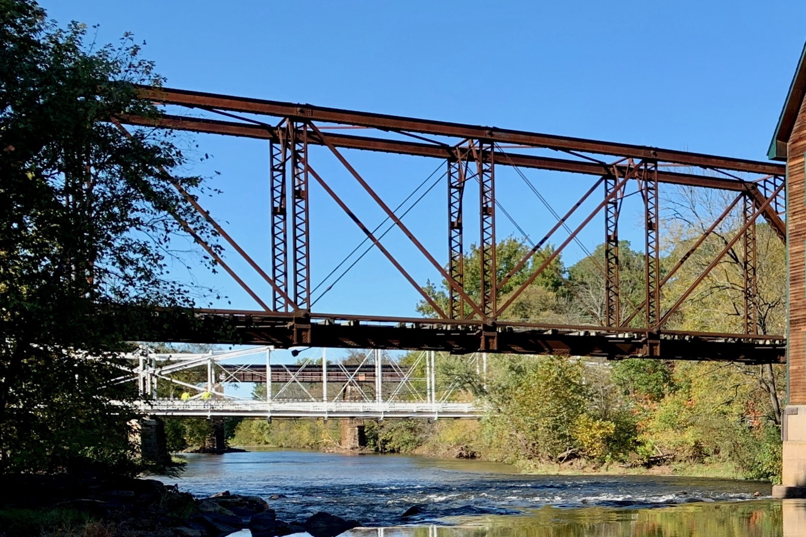
Every truss bridge runs on the same basic trick: cut a span into a network of straight members arranged as triangles, and geometry does most of the structural work for free. A rectangle can be pushed into a parallelogram without any of its four sides changing length, which is why a plain rectangular frame needs something extra, a diagonal brace, a rigid welded corner, poured concrete, to keep from racking sideways under a sideways push. A triangle has no such freedom: once the length of all three sides is fixed, the angles are fixed too, and the shape cannot deform without one of its sides stretching or compressing. Truss bridges exploit that single geometric fact at scale, tiling triangles between two long parallel members called chords, one running along the top of the structure and one along the bottom, connected by a web of vertical posts and diagonal braces, as Britannica's overview of truss bridge design lays out.
That geometry converts whatever crosses the bridge into two kinds of internal force running along straight members: tension, a member being pulled apart, and compression, a member being squeezed. In a simply supported truss under a downward load, the top chord generally ends up in compression and the bottom chord in tension, and each diagonal carries one or the other depending on which way it leans, a distribution explained in more mechanical detail by structural engineering firm Areté Structures. Because an idealized truss member carries only tension or compression and no bending, 19th-century engineers working entirely by hand could analyze a whole bridge with algebra, provided the truss met one condition, worked through step by step in TeachEngineering's lesson on truss force analysis: the number of members plus the number of support reactions has to equal twice the number of joints. Meet that equation and the truss is statically determinate, solvable joint by joint with nothing more than a pencil; fall short of it and the structure is an unstable mechanism that can collapse into a different shape entirely. Centuries earlier, and on a different continent entirely, Inca administrators solved their own hard computation problem by encoding numbers into knotted cord instead of paper, a reminder that working within whatever a material can actually do, not fighting it, is a much older engineering habit than iron bridges.
Two patents, four years apart, put wood and iron in opposite roles
The two most common historic truss patterns take their names from the men who patented them within four years of each other, and the reason their diagonal members point in different directions is not aesthetic, it is a direct read on what each material was actually good at in the 1840s. William Howe secured patents on his design in 1840 and again in 1846, pairing timber diagonal members with wrought-iron vertical rods threaded and tightened with nuts, as summarized by Iowa DOT's Historic Bridge Project; the wood took the compression, the iron took the tension, because sawn timber holds up well when squeezed along its grain but splits easily when pulled apart, while wrought iron does the opposite and was, in the 1840s, comparatively expensive to source in the long compression-bearing members a bridge needed.
Thomas Willis Pratt and his father Caleb, both from Boston, patented the mirror-image logic in 1844: keep the wooden verticals in compression, but swap the diagonal members to iron rods carrying tension instead, a reversal detailed in Structure magazine's history of the Pratt truss and by the History of Bridges project. The Pratt configuration became the more common highway and railroad pattern in the decades that followed, in part because as iron and then steel manufacturing scaled up through the second half of the 19th century, an all-metal Pratt truss let every diagonal do the one job iron was best suited for from the start.
Reusing the pattern without the logic collapsed a bridge in 11 years
The trouble starts when someone reuses a truss's geometry without preserving the material logic that made the geometry safe, and the clearest 19th-century case is the Ashtabula River railroad bridge in northeastern Ohio. Amasa Stone, an engineer and railroad executive who had built his career on Howe truss bridges in wood, adapted the same Howe pattern into what became the first all-iron Howe-type truss bridge in the United States, completed in 1865 to carry the Lake Shore and Michigan Southern Railway 165 feet across the Ashtabula River. The engineer Stone hired to draft and construct the design resigned partway through, on the stated grounds that the iron braces specified were too small for an all-metal structure built on a pattern developed for wood, according to PBS Western Reserve's account of the disaster.
The bridge carried trains for eleven years. On December 29, 1876, during a blizzard, the Pacific Express, two locomotives and eleven cars, was crossing the bridge when the span gave way beneath the second locomotive, dropping the train roughly 70 feet into the frozen river below; the wreckage caught fire from the cars' heating stoves. Of the roughly 159 passengers and crew aboard, a commonly cited figure of 92 died, though period and modern sources vary somewhat on the exact count, in part because dozens of the dead were burned beyond identification, per the tally kept by the disaster-history database usdeadlyevents.com. Subsequent investigation pointed to fatigue and brittle fracture at a flaw in one of the iron castings, the kind of failure mode a wood-tuned truss geometry, transplanted wholesale into a different material, had never been analyzed against.
Scaling the same triangle up killed 75 ironworkers in 15 seconds
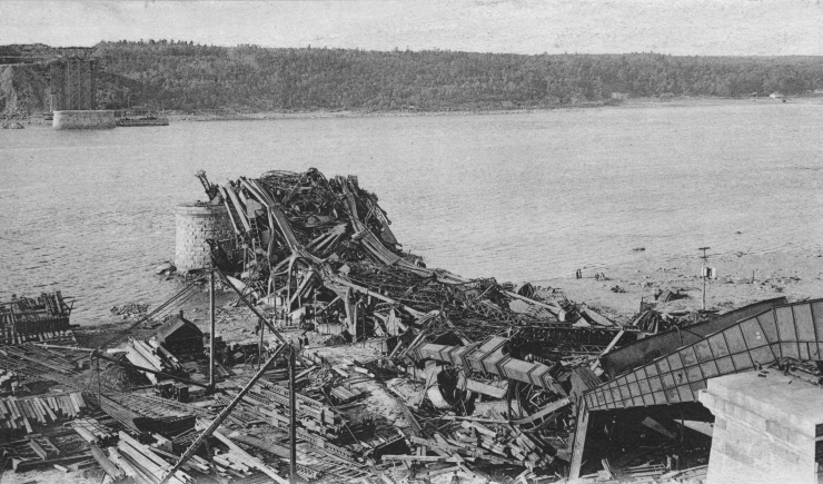
Ashtabula showed what happens when the material assumptions behind a truss stop holding; the Quebec Bridge, three decades later, showed what happens when the arithmetic behind a much larger one stops holding. The bridge under construction across the St. Lawrence River near Quebec City was designed as a cantilever truss, the same triangulated logic extended outward from piers on each bank with no support underneath the ends during construction, and it was set to be the longest cantilever span attempted anywhere up to that point, a clear span of roughly 1,800 feet, per the Canadian Encyclopedia's account of the disaster. Partway through construction the design was lengthened, and the consulting engineer overseeing the project did not require the bridge's own dead load to be recalculated for the new dimensions, while also permitting unusually high allowable stresses in the compression members, according to Canada.ca's official history of the bridge. The 1908 Royal Commission that investigated the collapse put the same point in its own official finding: "A grave error was made in assuming the dead load for the calculations at too low a value and not afterwards revising this assumption," and concluded overall that "the failure cannot be attributed directly to any cause other than errors in judgment on the part of these two engineers," rather than negligence or a gap in ordinary professional knowledge.
On August 29, 1907, with 86 ironworkers on the structure, a lower chord under compression buckled; the south arm and part of the central section collapsed into the river in roughly 15 seconds. 75 of the 86 workers died and only 11 survived; many of the dead were Mohawk steelworkers from the Kahnawake community near Montreal, a workforce that had become renowned for high-steel construction and was disproportionately represented on the crew that day. Reconstruction had its own failure: on September 11, 1916, the new center span being hoisted into final position fell into the river when a supporting steel casting failed, killing 13 more workers, as documented by Structure magazine's account of that second collapse. A rebuilt center span was successfully raised into place almost exactly a year later, on September 20, 1917, and the bridge opened to rail traffic that December, according to Canada.ca's official history of the bridge.

The 21st-century failure wasn't the geometry, it was a decimal point
The physics that makes a triangle rigid, and the accounting that keeps a truss's internal forces balanced, has not changed since the 1840s; what has changed is how many places an error can hide in a modern bridge's paperwork. The I-35W bridge that carried eight lanes of traffic 1,907 feet across the Mississippi River in Minneapolis was a steel deck truss, opened in 1967, and it collapsed on August 1, 2007, sending roughly 456 feet of the main span 108 feet down into the river. The National Transportation Safety Board's investigation found the cause was a design error dating to the bridge's original 1960s engineering by the firm Sverdrup & Parcel and Associates: gusset plates, the flat steel plates that bolt a truss's diagonal, vertical, and chord members together at each joint, were specified at roughly half the thickness the governing design code required at several critical nodes. The board's official finding named the specific cause directly: "the inadequate load capacity, due to a design error by Sverdrup & Parcel and Associates, Inc., of the gusset plates at the U10 nodes," which failed under the combined weight of prior bridge modifications and the traffic and construction loads present that day.
Investigators identified 24 under-designed gusset plates across the bridge, with the plates at four nodes on the main span, labeled U10, U10', L11 and L11', carrying roughly half the load capacity the code demanded, as reported by Commercial Carrier Journal's coverage of the NTSB findings. A confidently repeated figure surviving decades without anyone re-measuring it is not unique to bridges either: African wild dogs carried a widely cited 80 percent hunting-success rate for years before GPS collar data measured it at closer to 15 percent. That undersizing sat undetected through four decades of inspections and renovations until August 1, 2007, when the combined weight of accumulated deck resurfacing from earlier repairs, plus construction equipment and material staged on the bridge for ongoing maintenance work, exceeded what the thinnest gusset plates could carry. The NTSB found no evidence the U10 plates had pre-existing fatigue cracking or corrosion damage; the failure came from the original undersized plates finally meeting a load they had never had the margin to hold. 13 people died and 145 were injured.
Why the same triangle is still everywhere
None of these three failures, iron substituted for wood without re-deriving the truss logic at Ashtabula, an uncorrected dead-load calculation at Quebec, an under-specified connection plate at I-35W, came from the underlying idea of triangulation itself being wrong. In each case, a specific human decision, made under a deadline or cost pressure the historical record documents in some detail, let an assumption the triangle-based analysis depends on go unchecked. That is a large part of why the design has survived nearly two centuries of catastrophic case studies rather than being abandoned: a truss remains one of the most material-efficient ways to span a long distance, because triangulation lets every member carry load along its length without bending, which lets a truss bridge use dramatically less steel than a solid girder spanning the same distance with the same capacity.
Modern trusses are checked with finite-element software running thousands of load combinations no 19th-century engineer with a slide rule could have worked through by hand. It's the same computational approach that let researchers stress-test a Therizinosaurus claw in a 2023 study, treating a decades-old fossil the same way a modern gusset plate now gets treated: as a physical structure that can be modeled and checked, not just described. Gusset-plate capacity specifically became a mandatory, standardized checkpoint in U.S. bridge inspection guidance after the NTSB's I-35W findings. The triangle was never the problem; keeping every downstream calculation honest to the triangle's own logic always was, and that is a harder thing to guarantee across a bridge's paperwork, its decades of renovations, and the engineering firm reviewing all of it than it is to prove on a chalkboard.